There are actually many ways you can interface a stepper motor to your controller, out of them the most used interfaces are:
- Interface using L293D - H-Bridge Motor Driver
- Interface using ULN2003/2004 - Darlington Arrays
We will dicuss both connection techniques one by one. The above mentioned methods need 4 controller pins for interface.
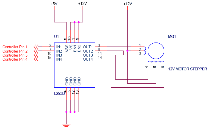
►Connecting Unipolar stepper using L293D
Please click on the image to enlarge it
As you see in the circuit above the four pins "Controller pin 1",2,3 and 4 will control the motion and direction of the stepper motor according to the step sequece programmed in the controller.
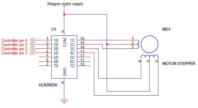
►Connecting Unipolar stepper using ULN2003/2004
Please click on the image to enlarge it
As already discussed in case of L293D, Here in this circuit too the four pins "Controller pin 1",2,3 and 4 will control the motion and direction of the stepper motor according to the step sequece sent by the controller.
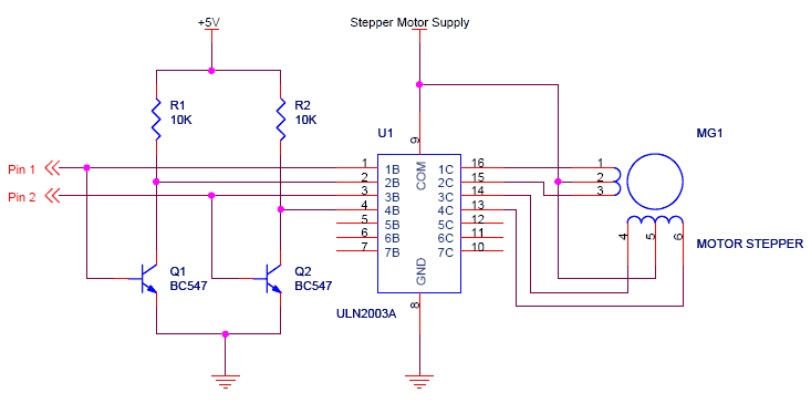
►2-wire connection for Unipolar Stepper Motor
We have seen the generally used 4-wire connection method for interfacing unipolar stepper motor, but we can simplify the design to make controller use less pins with the help of 2-wire connection method. The circuit for 2-wire connection is shown below.
Please click on the image to enlarge it
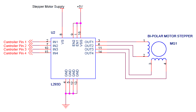
►Connecting Bipolar Stepper Motor
As we have studied that, Bi-polar stepper motors has 2 different coils. The step sequence for Bipolar stepper motor is same as that of unipolar stepper motors. The driving circuit for this require an H-Bridge as it allows the polarity of the power applied to be controlled independently. This can be done as shown in the figure below:
Please click on the image to enlarge it
Now we have seen the methods for connecting stepper motors with your microcontroller. So keeping these circuits in mind,we will now look at the programming of microcontroller to control stepper motors. This is discussed in the next section of the tutorial.


No comments:
Post a Comment